Saturday, September 19, 2015

Rebuilding Canopy

The canopy was not fitting well, and could use a little improvement. This is the nortoriously hardest part to build, so I'm starting over.

Replaced the WD- canopy side rail. You can see the holes are oblong and it was twisted too.


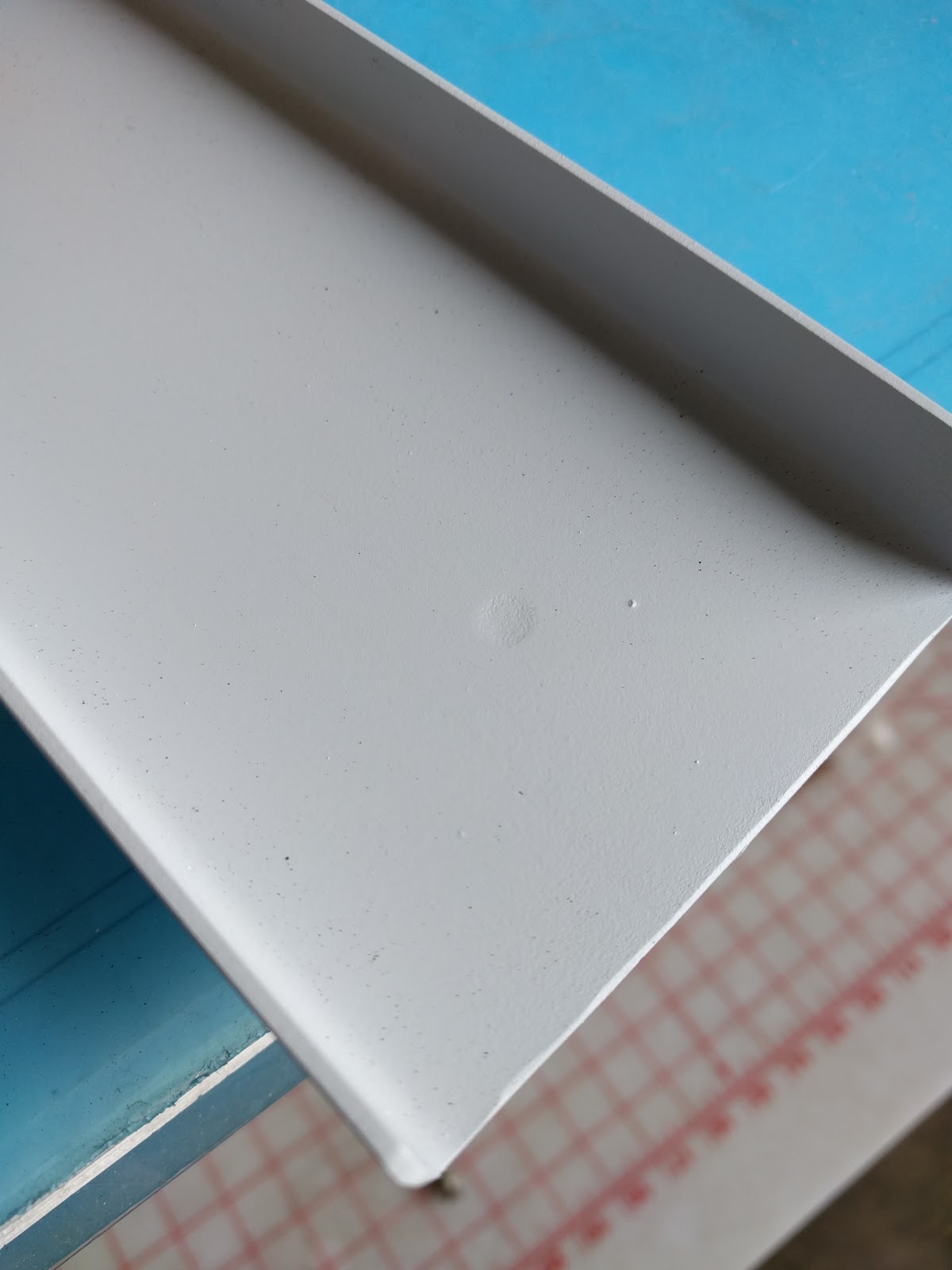
You can compare the old and new. I switched to water based, less hazardous primer. Unfortunately, it is not very grey, more of a white.

Also replaced the top skin of the canopy frame


This will take some work to get it all lined up in the existing holes of the forward canopy frame.

I also had to replace the rear canopy frame.


You can see that a tooling hole from production of the part is interfering with some drilled holes for rivets, so for my replacement parts I used some JB Weld to fill the holes

Hard to see here, but it's there.. not perfect but at least will provide some material to drill through.


Tuesday, May 26, 2015

Autopilot Hub wiring

The autopilot wiring runs to a central hub, provided by SteinAir. This simplifies the wiring runs and the CAN bus. However, I needed to determine the length of wire to run from the hub to each component.

Estimated Lengths
GSA 28 HUB to:
GDL 39R (ADB weather/traffic)

  • 20 AWG black/red (power/ground) ~20 ft.
  • 22 AWG shielded 2 conductor (signal) ~20 ft.

GTX 23ES (transponder): 

  • 20 AWG black/red (power/ground) ~15 ft.
  • 22 AWG shielded 2 conductor (signal) ~15 ft.

GSA 28 (A/P roll servo)

  • 20 AWG black/red (power/ground) ~20 ft.
  • 22 AWG shielded 2 conductor *2 (RS232 and CAN signal) ~40 ft. @ 20 ft. ea.
GSA 28 (A/P pitch servo)

  • 20 AWG black/red (power/ground) ~1.5 ft.
  • 22 AWG shielded 2 conductor *2 (RS232 and CAN signal) ~3 ft. @ 1.5 ft. ea.

Monday, May 25, 2015

Flap hardware and A/P install

Flaps

  • removed steel flap assembly and swapped bolt/nut configurations so bolt head is facing outboard vs. inboard. With the bolt head inboard, the nut can interfere and catch the rudder cable
  • removed vertical flap housing to replace 470-4-4 rivets with 426-4-4 flush rivets. This allows more clearance between canopy tip latch weldment tube and the flap housing F-705
Wing
  • Started install of GSA 28 autopilot servo motor bracket

Sunday, June 29, 2014

G3X Avionics Wiring

Worked on more wiring the LRU (line replaceable units) or blackboxes for the G3X avionics.


So far, I've just wired up the signal wires (which are the hardest parts). The power wires will come later when I get the actual instrument panel painted and install the switches into places. But these boxes connect to sensors and other boxes that will then display all the information on a screen (Electronic Flight Instrument System - EFIS - if you want to be fancy about it)


Once all this is done, just add the front panel and screen and the panel will  be finished.

Friday, June 13, 2014

Mounted subpanel, wiring work

Installed the subpanel and old instrument panel to see where the G3x black boxes and avionics would fit. As expected, the GTN 650 is longer than the space between the instrument panel and subpanel, so I'll have to cut out a section so it can fit.


I also kept going on the wiring. So far, most of the wiring has been point to point, meaning you simply put a wire on one end and connect it to another. I've been putting off wiring the CAN bus, which allows the avionics to communicate with another. Unfortunately, it's odd how it is depicted in the wiring diagram.

You can see that here I have to make some sort of splice, so that two wires come together and only one wire comes out (actually 3 in 2 out for the CAN lo pin and CAN termination pin). How you physically do this is beyond me. I suppose you can use solder sleeves that make a soldered joint for the wires. I suppose a butt splice would work too, but the idea is to avoid a method that increases the size of the joint too much. The solder sleeves shrink when heat is applied to them, not so much for the butt splice. 

Anyway, here's my first attempt - which I screwed up. 


The method for doing this came from the G3x install manual and this VAF post. Anyway, I'll need some help before I continue on with the CAN wiring. 


Monday, June 9, 2014

Magnetometer bracket, FAB, and subpanel

I made a bracket for the Garmin magnetometer. Apparently you can purchase one for $75 or make it yourself. No surprise, the guy who makes his own plane will make a bracket. Like anything else, I screwed it up the first time.

It came out OK, but was too thin with 0.025 in aluminum sheet. So, I remade it with 0.040 in sheet. Also, this time I used a 2.5 in hole saw to make it appear a little more professional.

What's crazy is the G3X manual specifies that you have to "Align the GMU 22 mounting rack’s forward direction to within  0.5° of the longitudinal axis of the aircraft".

So, I tried to make it as square as possible.  0.5° is a pretty small tolerance, but I think I got it. Here's how it came out:


Next up was the forward airbox. Yes, I had been putting this off. Basically, I shifted to bottom plate about 0.75 inches toward the copilot side so it would clear the mixture arm. I had to trim off the top of the filter because the captive bolts were poking the filter. Design is a series of compromises, I guess. I hate to hack up the filter but I was tired of fucking with it and something had to give.

Finally, I've been working on the subpanel now that I've started wiring the cockpit. The center section was the first up, and it came out well. I'm planning to install the cockpit instruments on the bench rather than in the actual plane (I'm not good at yoga).


The spotty green paint is zinc chromate primer. It's supposed to be a light coat, so while it looks stupid this is what you get. The factor claims you don't need any paint at all because the aluminum has an alclad layer that protects it from corrosion. Oh well, better safe that sorry.


Thursday, May 29, 2014

Overdue update

It's been a while since I updated the construction log. Most of the heavy lifting gets done on weekends, but the last few weekends have been busy: Chapel Hill, NC; Orange County, CA; Atlanta, GA; Austin... so. Lots of excuses. But, some progress:

PMag installation:


Simple and straightforward, plug and play.

I was not too pleased with the adapters. Plane spark plugs are 18 mm, but "regular" spark plugs with larger gaps (and better performance) are 14 mm. So, there EMag air sells adapters that can convert the size for you. Problem is, they are brass, or some sort of soft metal. The fit and finish is terrible - the threads were full of burrs and I had a really hard time getting them to thread into the cylinders without cross threading them. Anyway, I'd go with another vendor's if I had to do it again.

Also, I installed the engine temperature sensors for the G3X system: exhaust gas temp, cylinder head temp, and oil temp: